


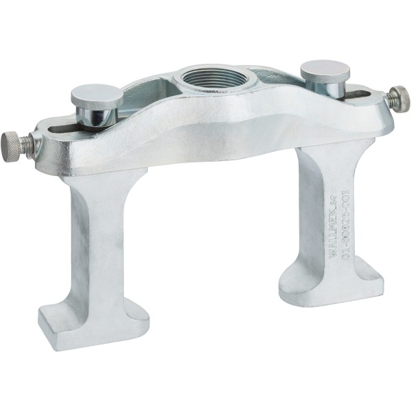


Article description
- Removing screwed wheel bearing units (4 bolts) at the front and rear axle
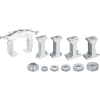
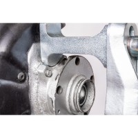
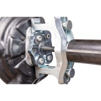
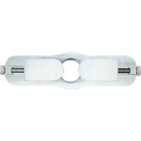
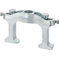
- Usage of the pressure feet on both sides ensures quick and easy adjustment at the steering knuckle
- Maximum loading capacity: 22 tonnes
- Adjustability guarantees usage with all models of screwed wheel bearing units with 4 bolts currently available on the market
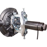
- Can be used directly on the vehicle
- For: VAG ∙ FORD ∙ MAZDA ∙ TOYOTA ∙ MITSUBISHI ∙ AUDI A4 ∙ A6 ∙ VW Passat ∙ ŠKODA Octavia ∙ SEAT Exeo etc.
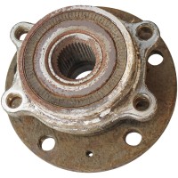
Design of Generation 3 wheel bearing
- Screwed Generation 3 wheel bearings are improved versions of the first and second generation wheel bearings. Due to various optimisations, these wheel bearings offer more complex functionalities. Maintenance and repairs are to be carried out with care and professional tools
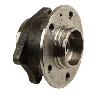
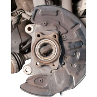
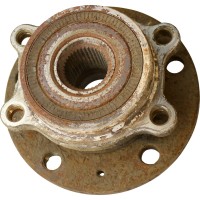
- Generation 3 screwed wheel bearings have two flanges. One flange serves as a wheel hub, the second is used to fix the bearing unit to the axle carrier. The wheel bearing is a compact and efficiently built unit and therefore cannot be split
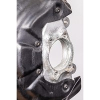
- Particularly in the case of aluminium steering knuckles, the bearing unit and steering knuckle may suffer severe corrosion. Without the suitable tool, damage will occur to the steering knuckle during removal
- A distinction is made between triple or quadruple screwed wheel bearings
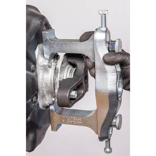
Step by step – split, screwed wheel bearings
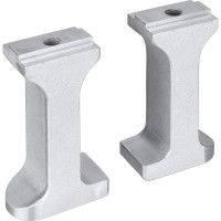
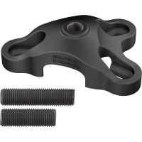
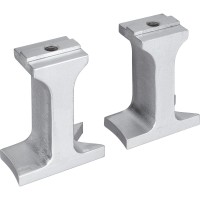
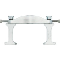
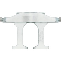
- Generation 3 wheel bearings require special pressure feet which are perfectly tailored to the fit of the bearing. If the pressure feet are not the right fit, power transmission is not possible because there is not enough contact surface
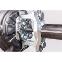
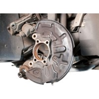
- Before the bearing is pressed out, the screws between the wheel bearing unit and the steering knuckle at the rear must be removed
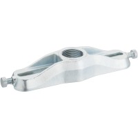
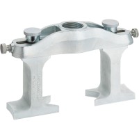
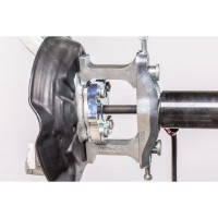
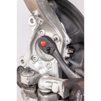
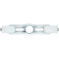
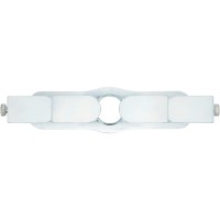
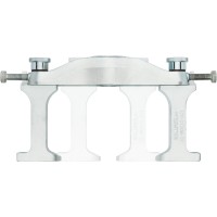
- In the next step, the pressure feet are centred with the crossbar. The same distances between the pressure feet must be observed
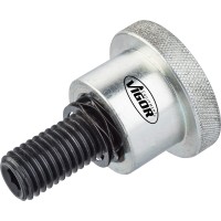
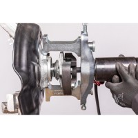
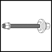
- The hydraulic cylinder or spindle can then be inserted and pushed through the crossbar and the bearing. The matching conical pressure piece is placed on the cylinder from the rear and locked with the lock nut. Now the bearing can be pressed out using a hydraulic pump
Downloads
Technical Specifications
- EAN
- 4047728037310
- Stückanzahl
- 7
- Wallmek-No
- 01-00026
- Steuersatz (für Artikel-Listenpreis DE Euro1)
- 19 %